Mux multiplexor multiplexer logic block cascading compuertas demultiplexor multiplexing Mux multiplexer verilog 2x1 code technobyte Multiplexer (mux)
Solved A)Implement a 2-to-1 multiplexer using three-state | Chegg.com
Mux circuitverse Multiplexer mux 8x1 logic July 2016 : vlsi n eda
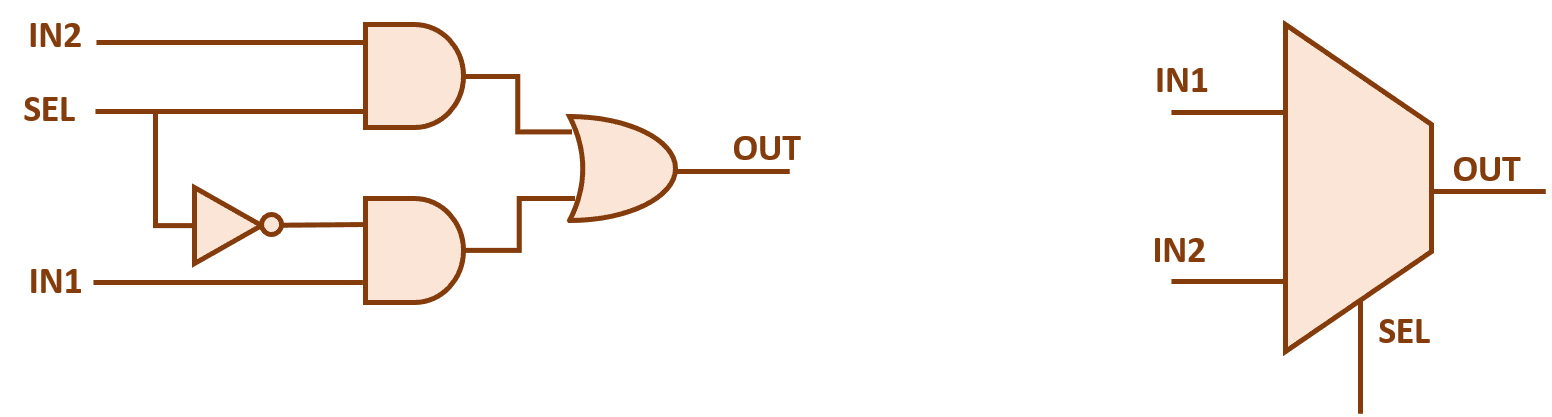
2x1 mux multiplexer diagram logic schematic symbol vlsi using gates inverter input figure eda logical
Multiplexer 4x1 circuits mux multiplexers encoder lines inputs combinational theoretically 2nMux logic gates using implementation courses Mux 2x1 multiplexer vhdlMux logic 8x1 multiplexer.
Mux using diagram block only 16 four logic digital slideplayer courtesy there common8x1 mux logic diagram : solved using the following circuit diagram Solved a)implement a 2-to-1 multiplexer using three-state16:1 mux : vlsi n eda.

Mux multiplexer application logic cascading multiplexing output electricalfundablog
Mux implementation using logic gates2x1 mux logic diagram / logicblocks experiment guide learn sparkfun com Mux multiplexer 8x1 diagram logic table schematic using truth input 16 vlsi 2x1 muxes symbol figure structure eda elchoMultiplexer (mux).
Multiplexer mux verilog 8x1 simplicity multiplexers implementedUsing state multiplexer implement three mux buffer buffers code vhdl write figure solved port maps based below Verilog code for 2:1 multiplexer (mux)Digital logic.

Digital logic
8x1 mux logic diagram / multiplexer 8 to 1 logic diagram 2002 chevy z71Verilog code for 8:1 multiplexer (mux) .
.


2X1 Mux Logic Diagram / Logicblocks Experiment Guide Learn Sparkfun Com

CircuitVerse - 4 to 1 mux
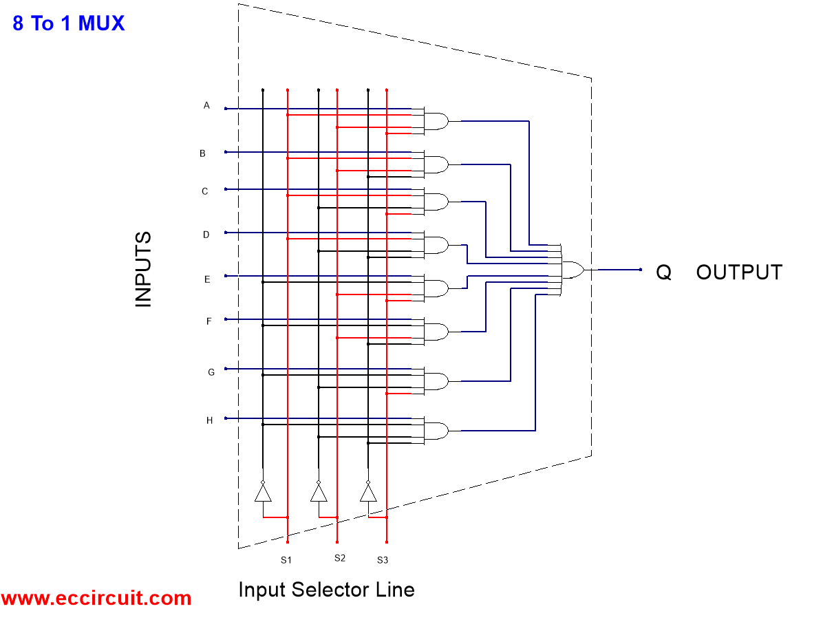
8X1 Mux Logic Diagram : Solved Using The Following Circuit Diagram

Verilog code for 8:1 Multiplexer (MUX) - All modeling styles

Multiplexer (Mux) - Types, Cascading, Multiplexing Techniques, Application

Solved A)Implement a 2-to-1 multiplexer using three-state | Chegg.com

Mux implementation using logic gates

Verilog code for 2:1 Multiplexer (MUX) - All modeling styles
July 2016 : VLSI n EDA