How cfl works compact electronic ballast Typical compact flash lamp ballast circuit [10,15] compact fluorescent Ballast fluorescent wiring fed
HOW A CFL ELECTRONIC BALLAST WORKS - YouTube
Wiring led ballast diagram t8 tube light lamp fluorescent fixture lights lamps tubes ballasts schematic lighting bar retrofitting read bypass Ballast wiring diagram ge fixture ft t12 foot change fluorescent electronic big flourescent installation proline electrical old tried without tombstones Circuit cfl ballast diagram electron composed seekic igbt electrical equipment
Fluorescent light ballast circuit diagram
Ballast filament preheating sourceInternational rectifier ltd Ballast cfl typicalOutput on florescent ballast?.
Single chip electronic ballast circuit with dimmable feature(pdf) contribution of the upfc in improving the quality of electrical power What is a ballast: types, function and replacement guideElectronic circuit ballast cfl indiamart.

Cfl electron ballast circuit composed of mpic2151p and powerluxtm igbt
Electronic ballastsBallast cfl electronic blocks How cfl works compact electronic ballastCfl ballast.
Cfl bulb circuit working explanationBallast electronic fluorescent diagram lamp capacitors electronics but serial electrical rectifier engineering exactly usable fully hope similar very stack Ballast fluorescent twin 120v 220vFluorescent ballast wiring diagram light t12 electrical ballasts wire lamp lights electronic starter replace power peculiar problem circuit led florescent.

Ballast wiring
Ballast fluorescent wiring cflBallast cfl Cfl ballast leds utilise driveBallast fluorescent typical cfl circuits frequency harmonic factor correction convert.
Fluorescent ballast wiring diagramBallast emi lighting energy saving diagram filter fluorescent electronic block control frequency improve reducing generated rectifier reductions simplify applies further Cfl bulb circuit working explanation20- 40w electronic ballast principle and maintenance under repository.

Cfl circuit bulb working ballast principle explanation diagram board
Ballast electronic circuit 40w principle maintenance gr next above click sizeTypical cfl ballast circuit Ballast cfl circuit typical diagramBallast wiring circuit uk420 post diagram 2007 boards.
Ballast fluorescent t12Ballast cfl Utilise cfl ballast to drive ledsHow a cfl electronic ballast works.

Ballast circuit electronic diagram dimmable single chip ic homemade feature
Circuit ballast cfl fluorescentCfl electronic ballast circuit at best price in new delhi by puri Electronic ballast with current source filament preheating.Fluorescent light ballast circuit diagram.
Fluorescent ballast wiring diagramHow cfl works compact electronic ballast How compact fluorescent lamps work-and how to dim them19 beautiful ge ballast wiring diagram.

Ballast circuit function 28w t5 figure7 apogeeweb
Typical cfl ballast circuitFluorescent dim cfl ballast impossibile realizzare trasmutazione lampadina compatta fluorescente dimming esperimentanda Cfl circuit bulb working explanationCfl electronic insight circuitry.
120v, 220v electronic ballast circuit for twin 40 watt fluorescent tubes .


rectifier - Serial capacitors in electronic ballast of a fluorescent

Utilise CFL ballast to drive LEDs - EDN Asia

International Rectifier Ltd - Reducing ballast-generated EMI to improve

Output On Florescent Ballast? - Electrical - DIY Chatroom Home
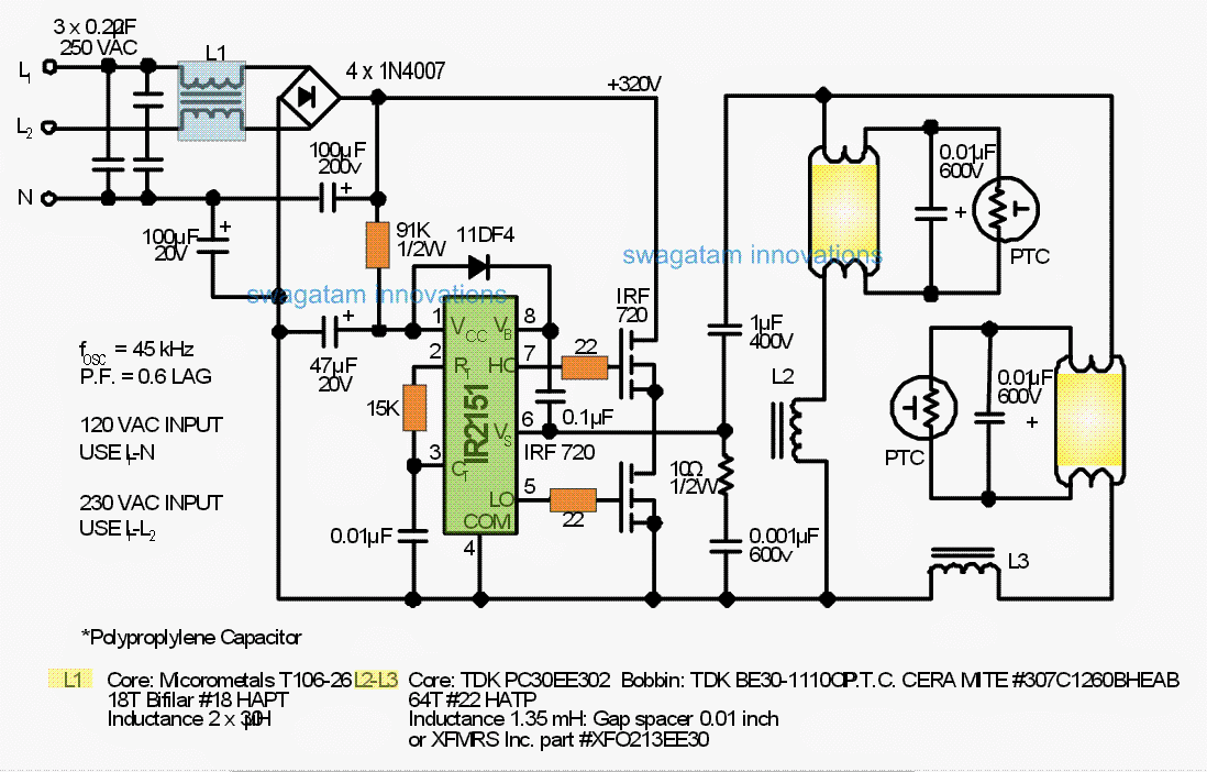
120V, 220V Electronic Ballast Circuit for Twin 40 Watt Fluorescent Tubes

CFL electron ballast circuit composed of MPIC2151P and PowerLuxTM IGBT