Mux multiplexer verilog 2x1 code technobyte 2x1 mux logic diagram / logicblocks experiment guide learn sparkfun com Mux 4x1 2x1 multisim
8X1 Mux Logic Diagram : Solved Using The Following Circuit Diagram
4x1 mux using 2x1 8x1 multiplexer Mux logic 2x1 gate circuit
Mux 8x1 logic 2x1 implementation truth
Where computers come fromMantra vlsi : mux 4x1 and 2x1 (multiplexer) 8x1 mux logic diagram : solved using the following circuit diagramVerilog code for 2:1 multiplexer (mux).
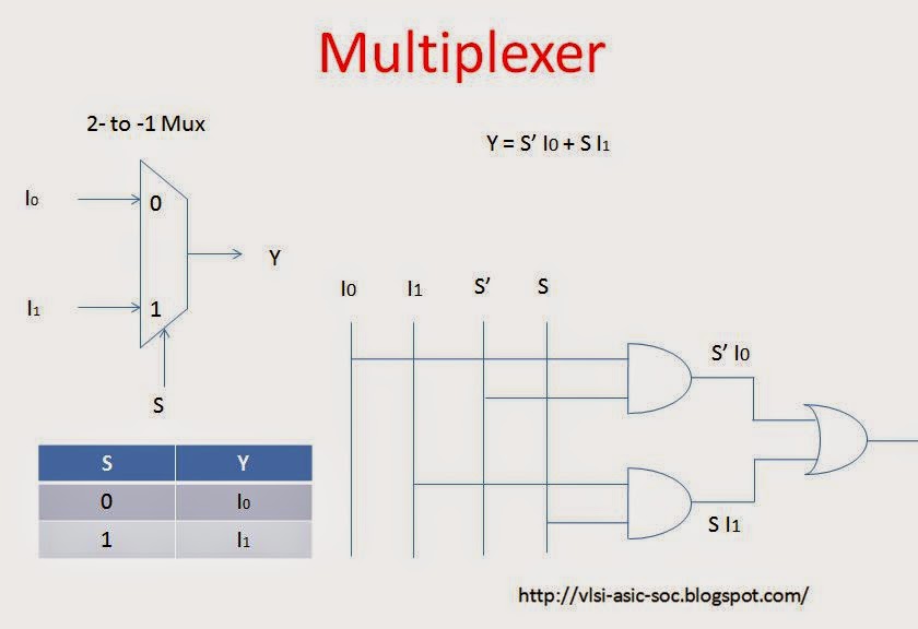
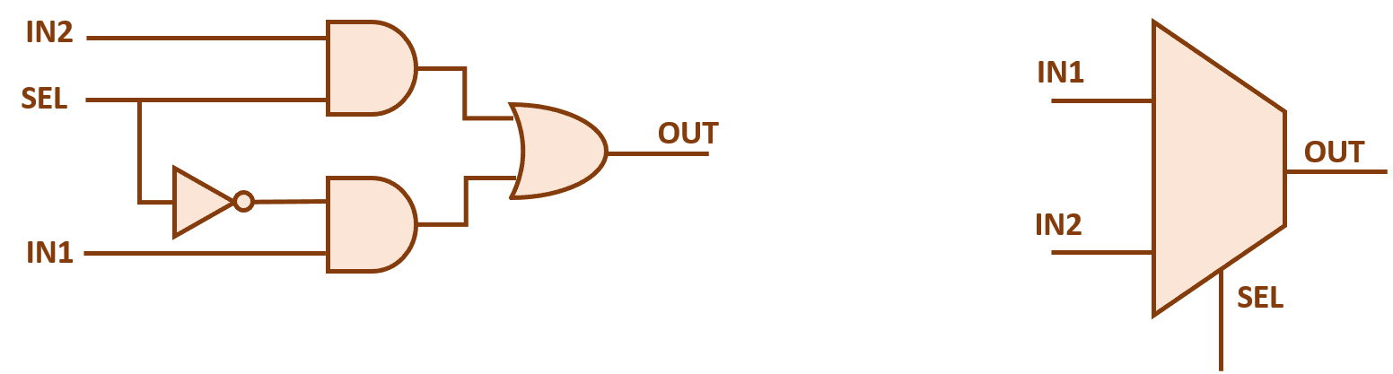
2x1 mux : vlsi n edaMux 2x1 multiplexer 4x1 vlsi mantra 8x1 multiplexer mux 32x1 implementation circuit elcho2x1 mux multiplexer logic diagram schematic using gates symbol vlsi input inverter figure eda logical label.

Mux 2x1 multiplexer logic table
.
.


2X1 Mux Logic Diagram / Logicblocks Experiment Guide Learn Sparkfun Com

Verilog code for 2:1 Multiplexer (MUX) - All modeling styles
Mantra VLSI : MUX 4X1 and 2X1 (Multiplexer)
2x1 mux : VLSI n EDA

8x1 Multiplexer | Wiring Diagram Image

8X1 Mux Logic Diagram : Solved Using The Following Circuit Diagram