Schematic and layout of 1x 2-input nand gates with (a) glb applied to 2-input nand gate Digital logic
C-MOS logic integrated circuits - Lab4Sys.com
File:7400 quad 2-input nand gates.png Nand gate diagram 74hc00 ttl input quad 7400 pinout latch using gates nor push pull octoprint funny four has Nor nand produces
74hc00 / 74hct00, quad 2
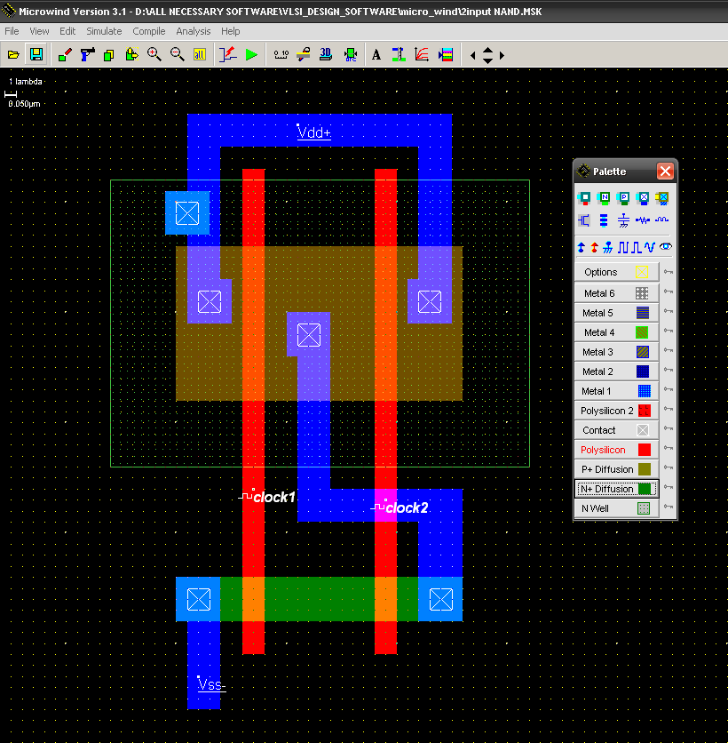
In a 2-input nand, which will be faster when switching: when the aInput nand gate three microwind stick diagram schematic tutorial part Draw circuit diagram of 2 input ttl nand gateNand nor gate transistor logic cmos why input circuit nmos size gates preferred diagram over level logical output industry capacitance.
Vhdl tutorial – 5: design, simulate and verify nand, nor, xor and xnorTtl gate nand diagram circuit input draw Mos logic cmos nand gate circuits lab4sys implementationNand eeweb.

Nand circuitverse
Nand input transistor cmos logic transistors implementation leakageNand cmos gate input layout microwind pspice also [solved] design a circuit that produces a 2-input nor gate functionNand cmos input single delay characterized conventional jayanthi.
Satish kashyap: microwind tutorial part 5 : three (3) input nand gateTtl nand explain truth transistors Cmos 2 input nand gateC-mos logic integrated circuits.

Engineering concepts: 4-input nand gate using 2-input nand gates
Nand schematic gates 1x glb appliedTwo input nand gate. basic two input nand gate: figure 3 show the E77 . lab 3 : laying out simple circuitsNand input gate using gates implementation logic circuit concepts engineering.
Nand 7400 input quad gates gate file wikimedia digitalA). a conventional 2-input cmos nand gate characterized by a single Nand layout gate simple figure laying circuits larger version clickDraw the circuit diagram of ttl nand gate and explain its working with.

Nand nor xnor vhdl xor simulate circuits verify logic
Nand cmos pmos nmos logic input transistors nor parallel transistor implementation logica turns switching which quasi delay insensitive gatter function .
.


CircuitVerse - 3 input NAND to 2 input NAND

Draw circuit diagram of 2 input TTL NAND gate
![[Solved] Design a circuit that produces a 2-input NOR gate function](https://i2.wp.com/www.coursehero.com/qa/attachment/14800230/)
[Solved] Design a circuit that produces a 2-input NOR gate function

Schematic and layout of 1X 2-input NAND gates with (a) GLB applied to

digital logic - Why is NAND gate preferred over NOR gate in industry

2-input NAND Gate - EEWeb
CMOS 2 input NAND gate | All For Students

VHDL Tutorial – 5: Design, simulate and verify NAND, NOR, XOR and XNOR