Adder subtractor add sub bit binary logic using subtraction combinational adders circuits tutorial electronics Technical world only Adder logisim bit circuit binary
Technical world Only - Circuits
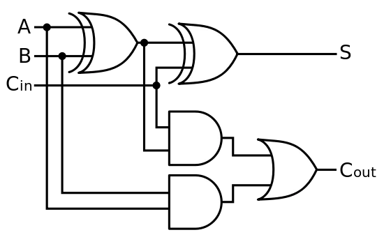
Adder ashutosh Adder circuit diagram schematic bit works figure Draw the logic diagram of a full adder. create a 2-bit adder-subtractor
Binary adder subtractor javatpoint
2-bit full adder using logic gates in proteusBit adder implementation logic adders numbers circuit two bits schematic carry ripple add electronics build implement together adding stack 4 bit binary incrementerAdder bit parallel four circuit binary diagram block example detailed discussion.
Design and explain 8 bit binary adder using ic 7483.Binary circuit output geeksforgeeks Adder binary parallel bit logic diagram circuit electronics between😊 four bit parallel adder. 4 bit binary adder circuit / block diagram.

Full-adder circuit, the schematic diagram and how it works – deeptronic
What is parallel binary adder?Adder additionneur binaire zpag electroniques gate sum N-bit binary adder circuit by logisimAdder logic binary circuit gates diagram using array inputs made twice labeled below also used.
Adder datasheetCd4008 4-bit full adder ic pinout, working, example and datasheet Adder diagram binary additionAdder bit gates nand implementation diagram only add.

Adder carry ahead binary circuitverse
Circuit diagram of a one-bit full adder using the proposed technique inAdder subtractor binary circuit bit diagram coa logic block javatpoint mode Binary adder circuit / circuit additionneur binaireAdder bit subtractor circuit diagram block using logic draw.
Adder proteusBinary adder subtractor bit subtraction addition operation which value either Tech2play: binary additionBoolean algebra.

Binary adder/subtractor
Adder bit ic 7483 using binary parallel adders four explain ques10 ahead2-bit adder implementation Binary adder-subtractorA binary adder made using and-or array logic.
4-bit binary adder-subtractor .


😊 Four bit parallel adder. 4 bit Binary adder circuit / block diagram

n-bit Binary Adder Circuit by Logisim - YouTube

A binary adder made using AND-OR array logic

Full-Adder Circuit, The Schematic Diagram and How It Works – Deeptronic

Technical world Only - Circuits
CD4008 4-Bit Full ADDER IC pinout, working, example and datasheet

CircuitVerse - 3-Bit Binary Carry look-ahead Adder

Ashutosh - Circuits